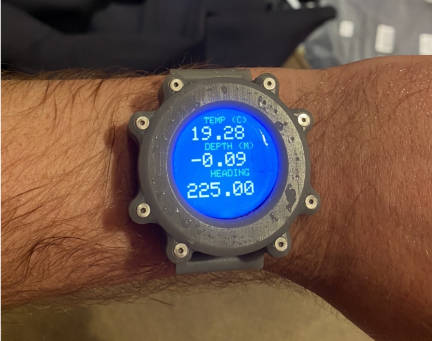
D3PTH - Design And Build of A Freediving Smart Watch
I Led a Team to Design And Build A Freediving Smart Watch That Won 2nd Place at MakeMIT 2021. We did it in 16 days, here is how:
Important context: Freediving - the sport or activity of diving underwater without the use of breathing apparatus, especially in deep water.
What is D3PTH?
D3PTH is a freediving smart watch/computer that a friend and I built as part of MakeMIT link. We built D3PTH because we though it would be a fun and challenging embedded systems project within the constraints of the MakeMIT hackathon. The constraints were a 16 day build + demo window and a $500 budget. After being accepted into MakeMIT, we got to work on a plan.
My role on the team was project lead. I worked on the electronics, mechanical engineering, firmware, and physical prototyping (3D printing, soldering etc).
Why do you need a freediving computer?
- Keep track of surface interval to prevent shallow water blackouts
- Stay informed about your depth, dive speed, dive time, and other metrics
- Log dives for future review + training
Timeline
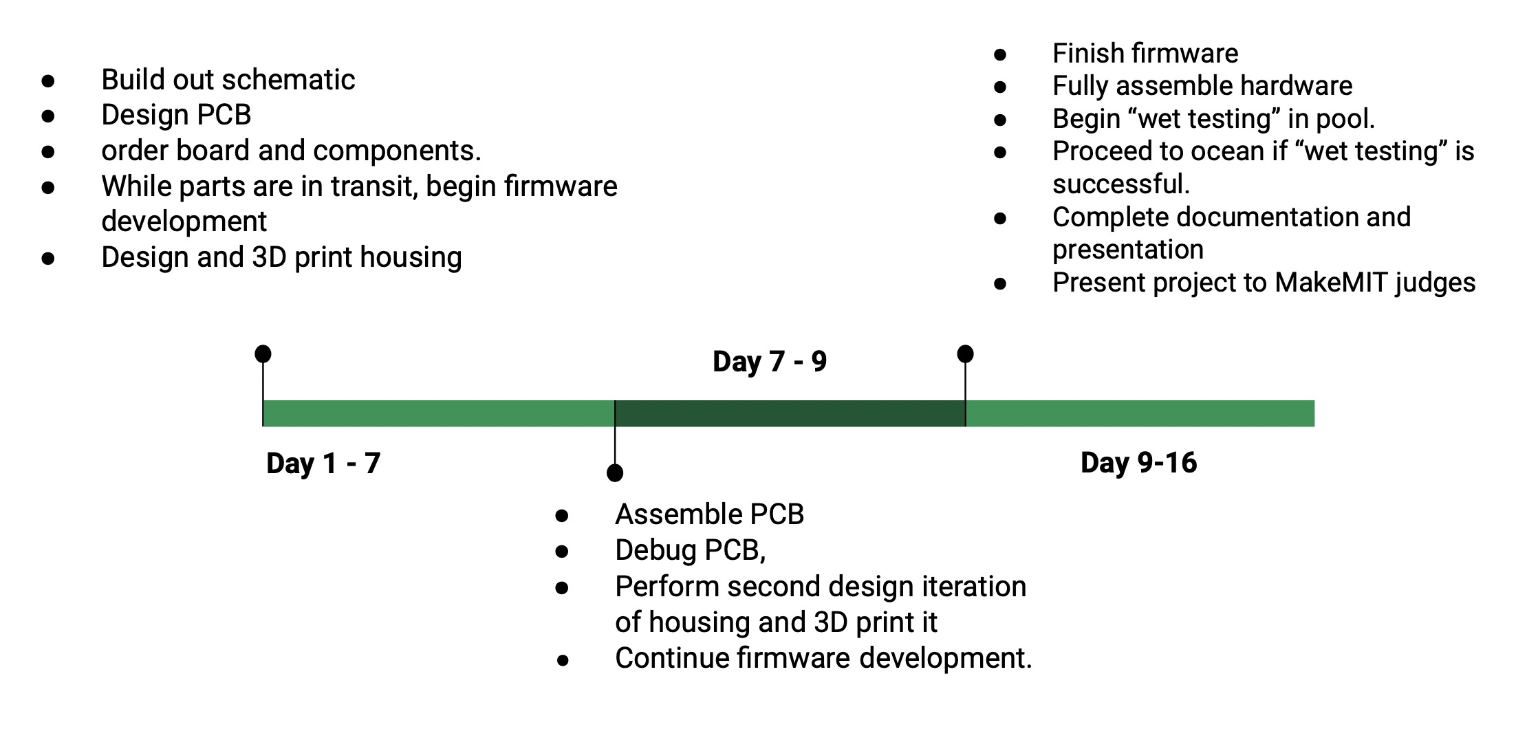
Design Phase
We identified early on that there were three elements of the design we need to get right to be successful.
- Electronics
- Mechanical Design (pressure vessel)
- Firmware
Electronics
Since our time line was tight, we started working on the electronics first. While we could afford to iterate on the firmware and mechanical design daily, getting a PCB made and shipped takes 5-10 days. The 5-10 day lead time for the electronics meant we only had one shot to get it right. Once the electronics were designed and ordered we could then reallocate our time to iterating on the firmware and mechanical design.
Our first step was creating a rough set of requirements for the electronics. We landed on the following:
- Color screen
- IMU based user interface (no buttons)
- ESP32 MCU (we had experience with this MCU)
- Wireless Charging (no propriety charing dock)
- Haptic feedback for in dive depth monitoring
- Dive logging
- Wireless dive log export over bluetooth
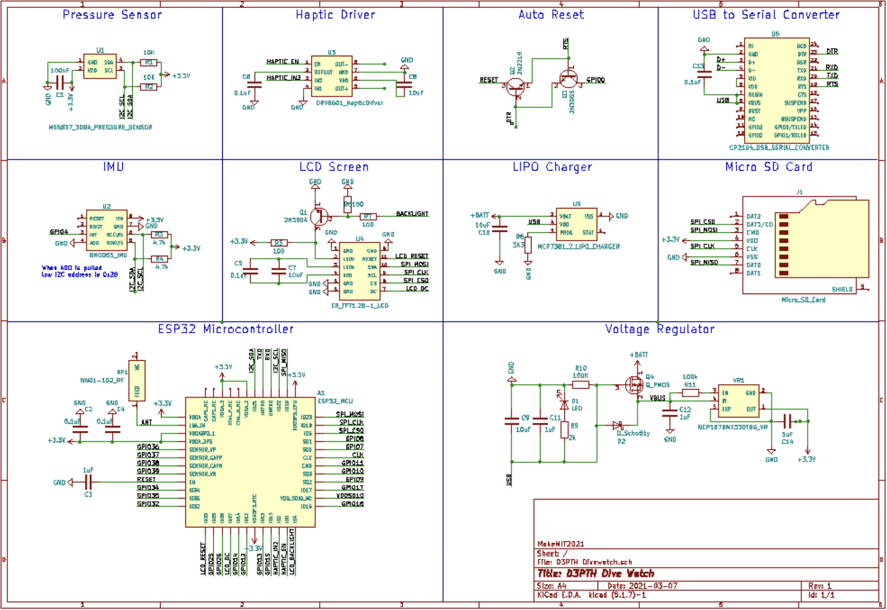
We then created a basic high level electronics schematic:
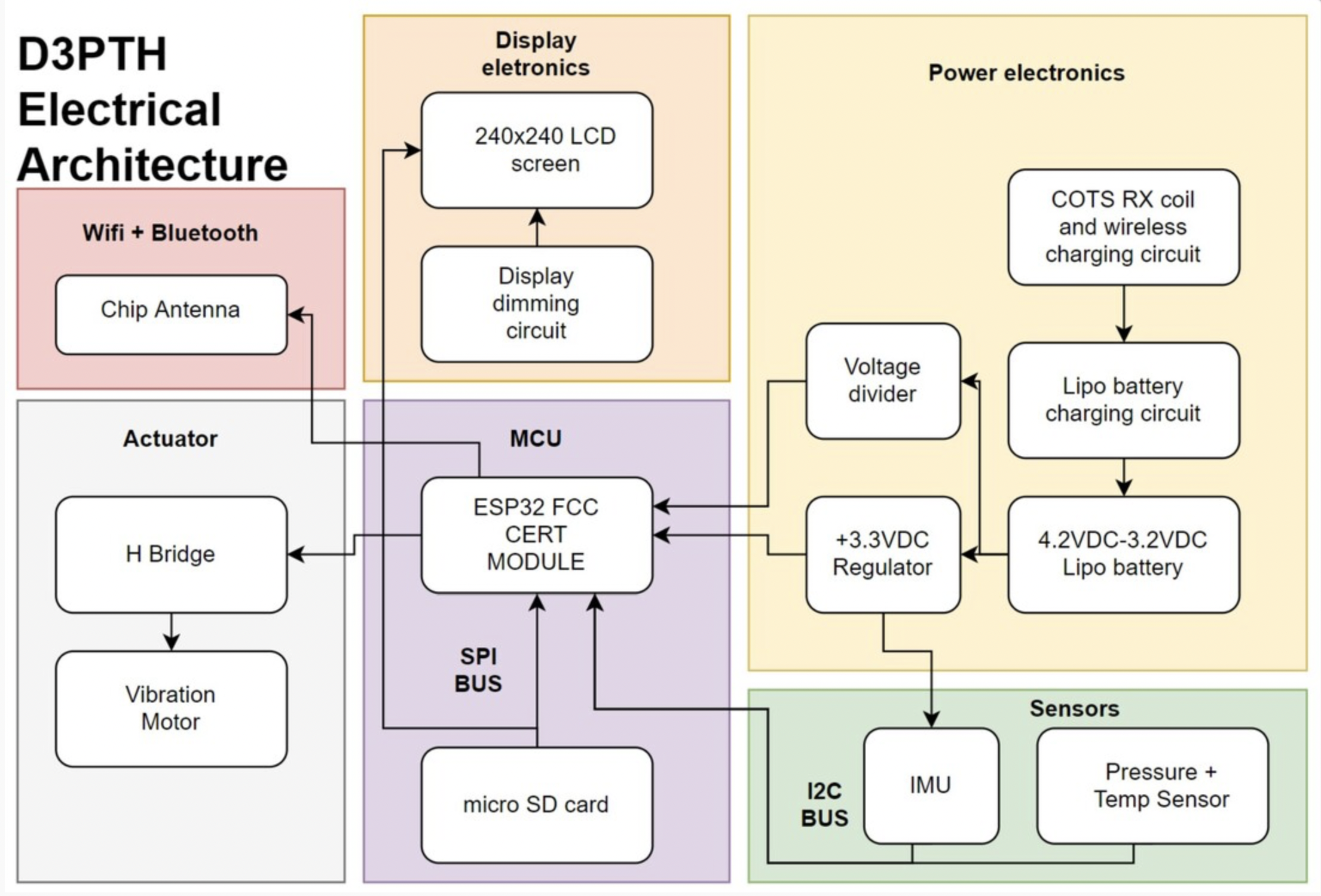
After some googling we found our screen: GC9A01 Driven 240 x 240 circular display
It took a bit more research, but we were able to come up with a parts list and started working on the schematic. After the schematic was done, we moved on to PCB design and designed the shape of the PCB to fit the diameter of the screen we selected. The dimensions of the mechanical design would also be derived from the screen + PCBA.
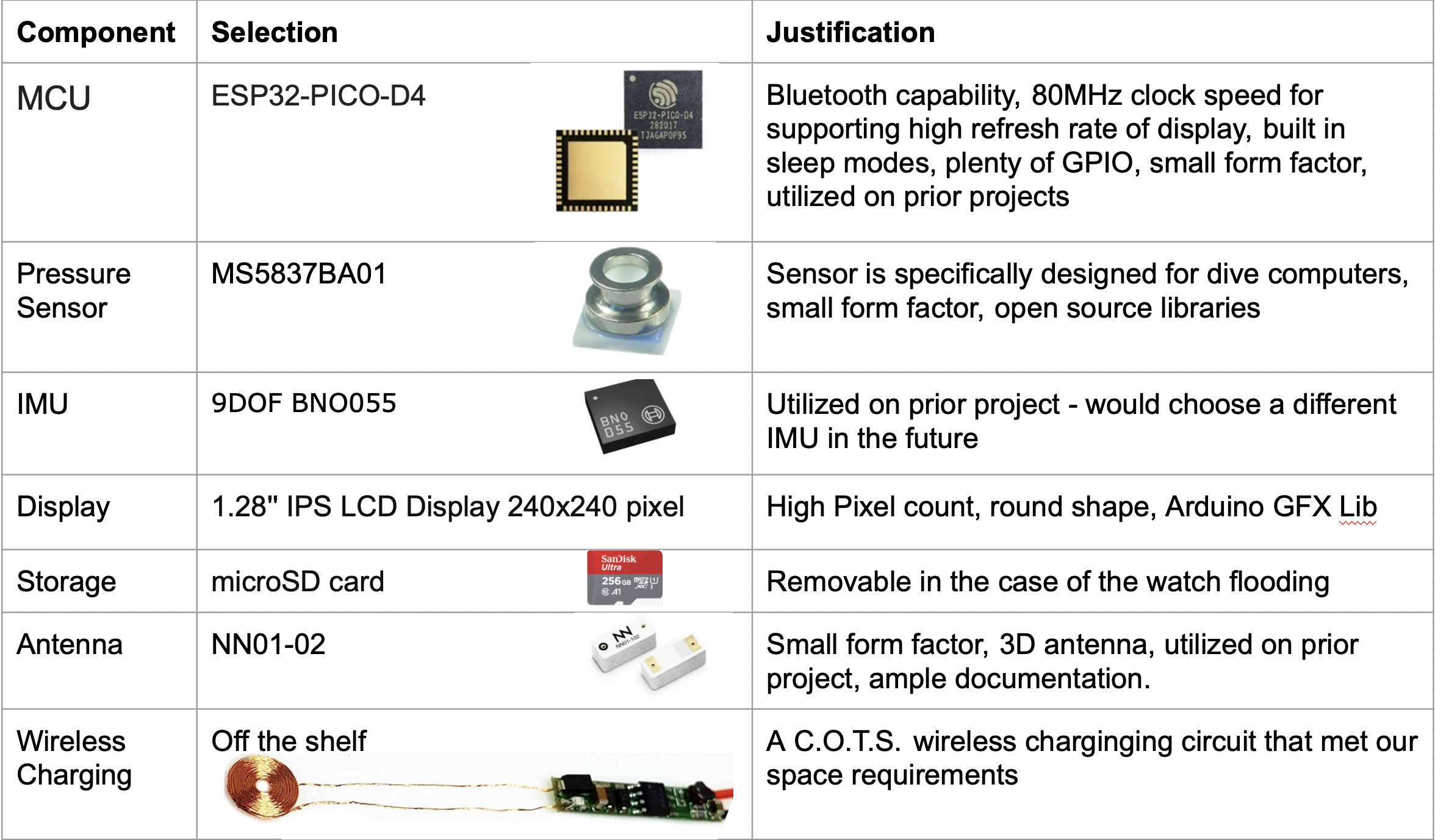
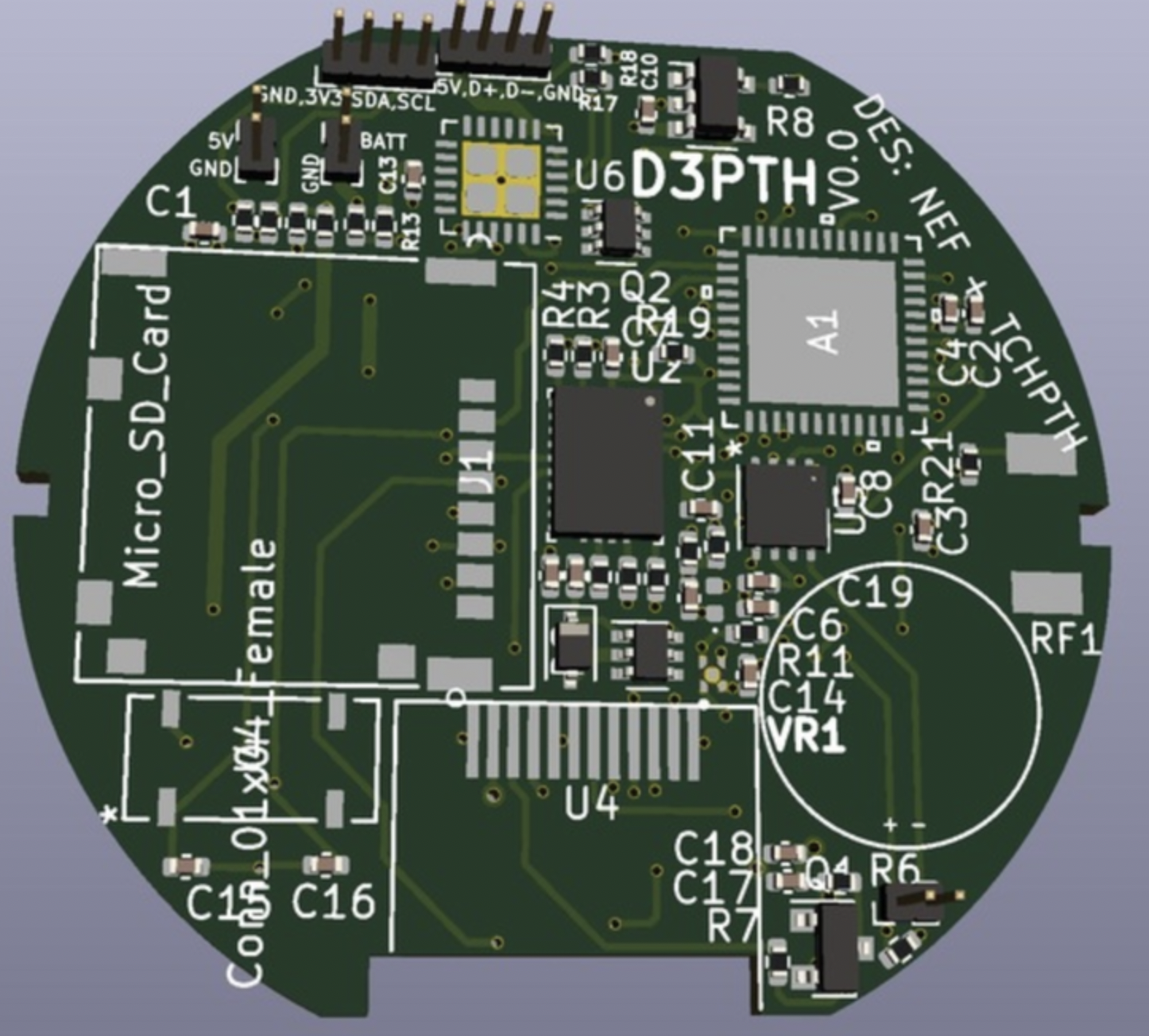
Our PCBA process roughly followed these steps:
- PCB outline was created first in the Solidworks assembly to ensure the PCB would fit in the housing
- Rough component placement sketch made in Solidworks showed I had to switch from 0602 size resistors and capacitors to 0402
- 4 layer from top to bottom: signal, ground plane, signal and 3.3V, signal
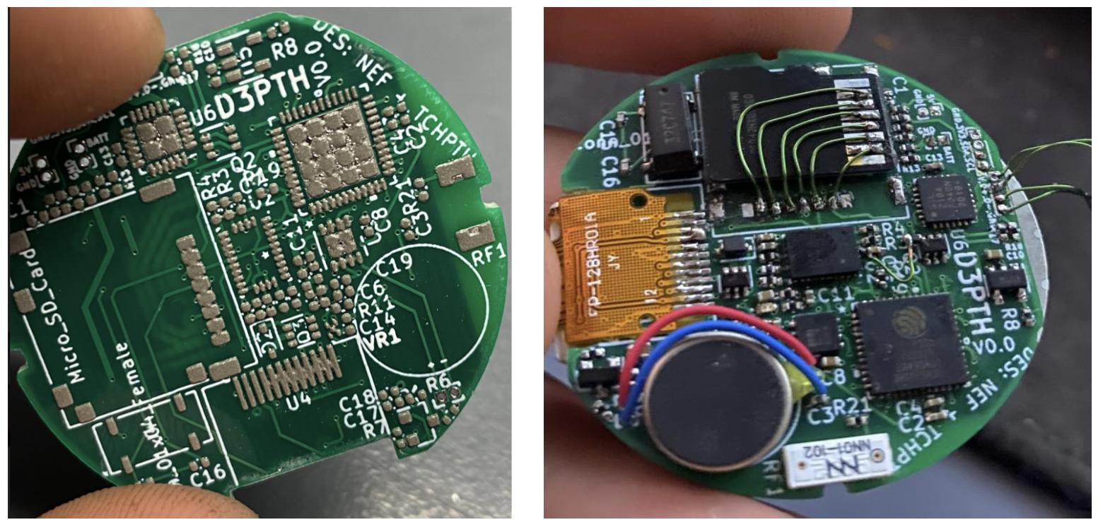
- Antenna placed on edge of board as per data sheet recommendations. Vibration motor placement adjacent to antenna is not ideal, but did not interfere significantly with bluetooth connection.
- Mistakes with missing traces and SD card slot rectified with 28AWG jumper wire
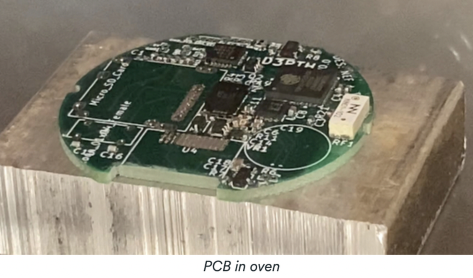
- Utilized a SMT stencil, and toaster oven to create solder joints
- Initial testing showed power draw during dive mode is 60mA, battery size is 400mA, max operating time is 6.5hrs.
 |
 |
Mechanical Design
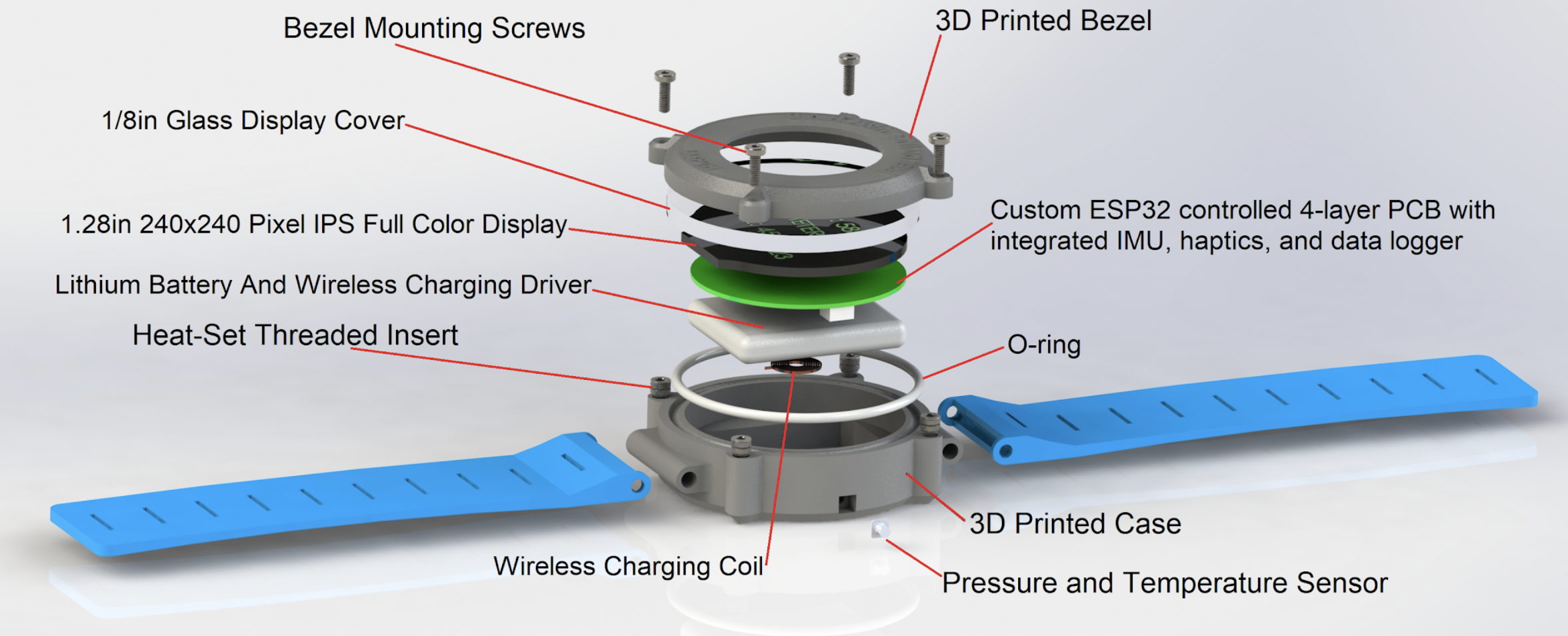
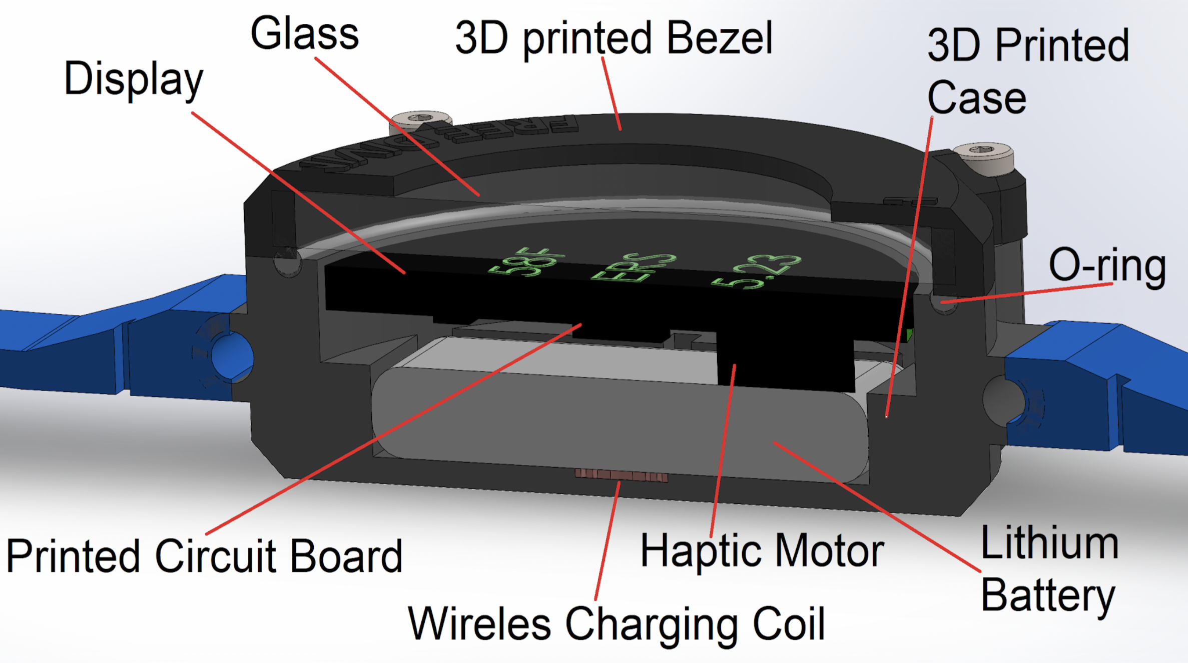
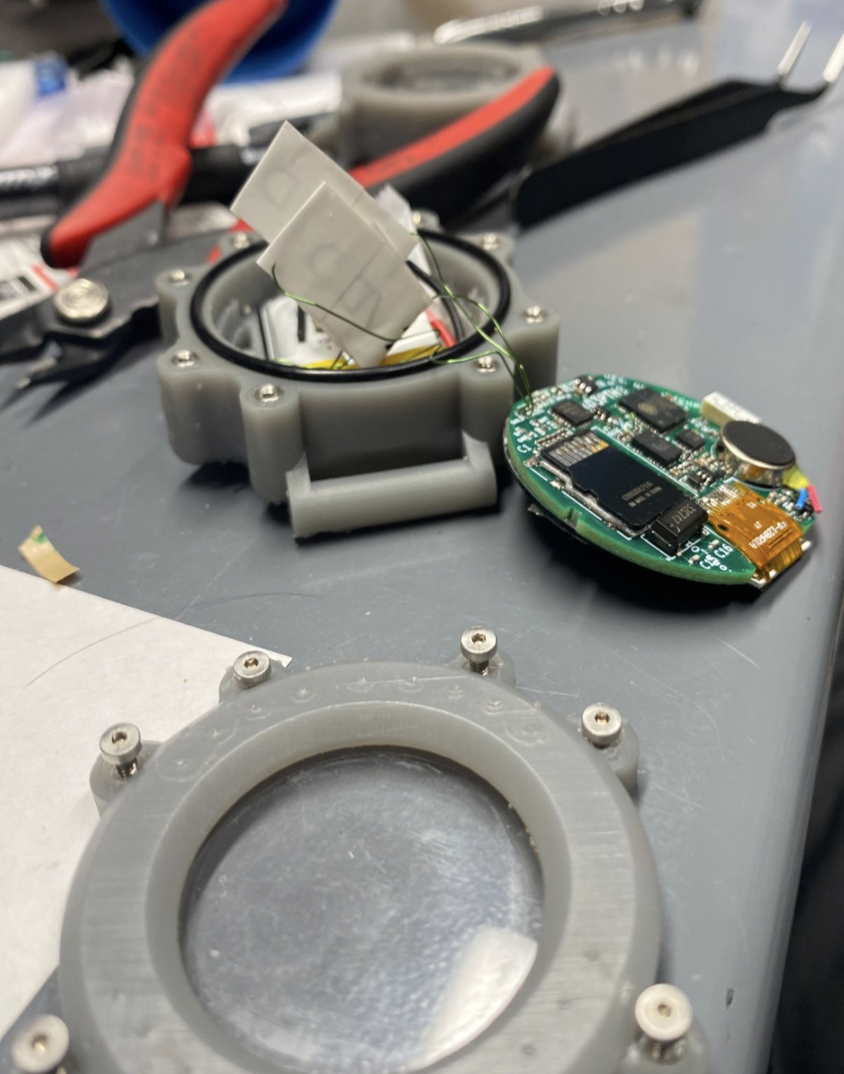
Now that our electronics had been designed and ordered, I moved on to the mechanical design. The casing had a few key requirements. It had to be water proof to 50ft, had to have a place for the wrist strap to attach, and had to have a glass side for viewing the screen. Based on the those requirements I chose to use SLA 3D printed parts because they are watertight without post processing. After a couple hours in Solidworks I had the first iteration done:
 |
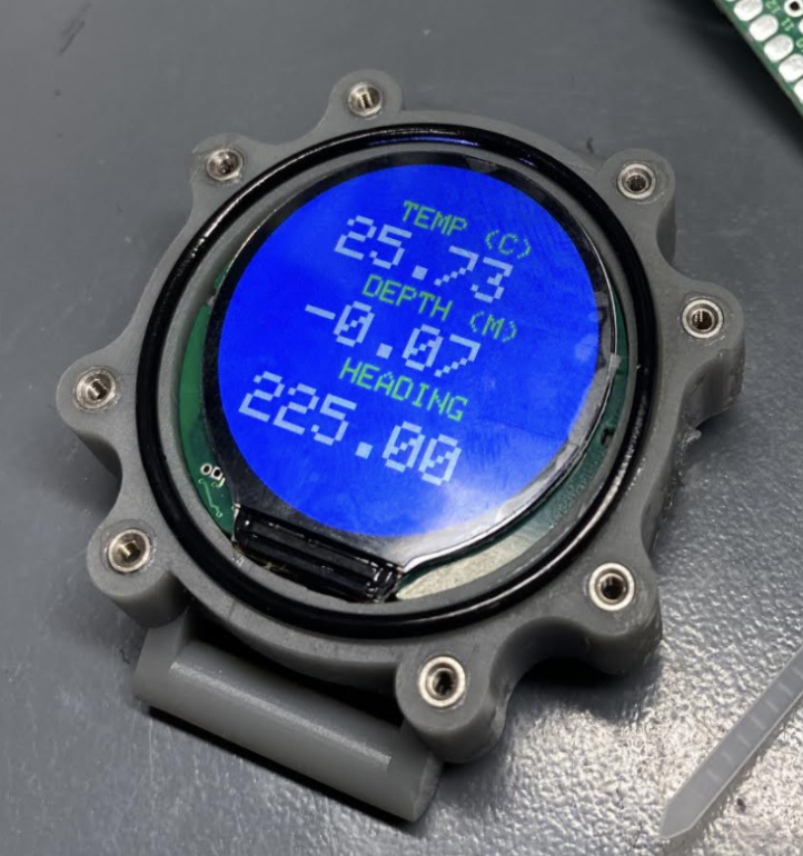 |
On the left is the V1 casing and on the right is V2. A design iteration was required because the bezel clamping the glass down onto the o-ring was not rigid enough to create a proper seal. As a result of this I increased the thickness of the bezel and added additional mounting points.
Firmware
While we waited for our electronics to be manufactured and casing to be 3D printed we started on the firmware. We tried to keep things as basic as possible in order to ensure we would be able to deliver a functional demo. We narrowed down our feature list to:
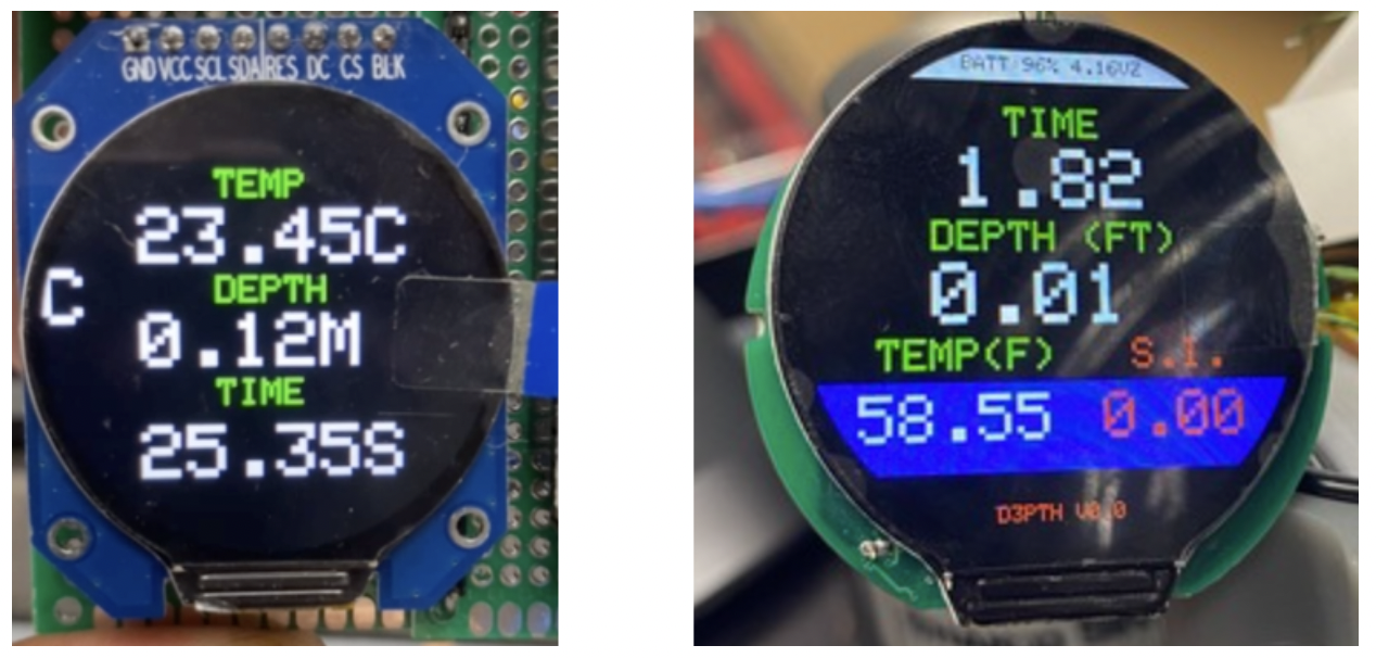
- Display relevant information (depth, water temperature, surface interval, heading)
- sample pressure at 2hz
- haptic feedback for reaching a preprogrammed target depth
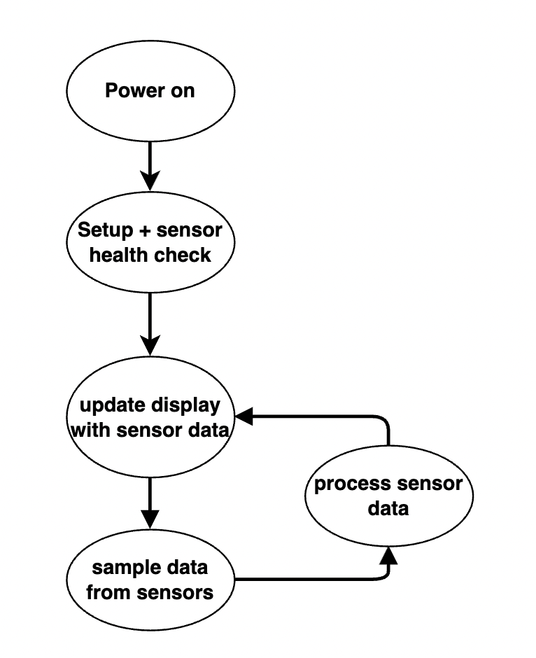
We skipped working on a sleep mode or charging mode as those features weren’t necessary for the demo. We implemented our code in C++ with the Arduino frame work through Platform.io. The code runs in a super loop:
Lessons learned
Integrating the mechanical, electrical and software components of the project turned out to be a challenge, and we worked until the last minute to get our demo ready. Some of the key challenges we faced were:
- Space constrained PCBA’s are psychically difficult to work on and test due to small size
- Some of the foot prints we used on the schematic were wrong an dded to be double checked
- The supply of some IC’s was low and we had to desolder IC’s from evaluation boards to get the parts we needed.
Lessons learned:
- Utilize a checklist when reviewing PCB for errors prior to sending design files to manufacturer
- Use remote serial to UART programmer instead of including a serial to UART IC on space constrained designs
- Use SPI flash IC’s instead of SD on space constrained designs
- Have the PCB assembled by a robot if the budget allows
- Always use connectors, avoid solder pads for frequently disconnected wires
- When designing an o-ring groove, design the groove for an o-ring under compression vs an uncompressed o-ring
- Switching away from the Arduino IDE to Visual Studio + Arduino extension
- Don’t desolder IC’s from an evaluation board to compensate for the global chip shortage. Find a new IC
Results
In the end we were able to present a demo of our project and won 2nd place! We were proud of our effort over the ~ 2 weeks allotted for the hackathon. I’ve continued this project and you can check out the V2 version here
